I developed this fish detection algorithm during my internship at BIOS (Bermuda Institute of Ocean Sciences). This program is to be used on deep-sea baited camera footage to remove frames without movement in an attempt to cut down on the number of empty frames that the human classifier has to look at, thus saving time in video analysis.
Description
This algorithm uses OpenCV to convert the video into a series of successive grayscale frames. It then takes two consecutive frames and subtracts the pixel values of the previous frame from the pixel values of the current frame. After doing some computer vision thresholding, blurring, and pooling, the result is a map of everything that has changed between the two frames. The algorithm then takes the ratio of motion frames to total frames, and if this number lies inside of a predetermined range (which was fine-tuned through testing), the two frames will be considered motion frames. After determining these motion frames, the algorithm determines the time when each of these frames occurred, does time-based processing to filter out noise, and joins time periods together if the gap between them is sufficiently small. Finally, the algorithm writes these time periods in a text file and uses moviepy to create clips of these motion periods.
Skills Needed/Learned:
Python Computer Vision Moviepy
Results:
The left video is actual footage captured from a camera that I deployed, and the right is my motion map applied to it.
Future:
This program is being used by the people at BIOS to detect fish motion, reducing the manual analysis time by 80%. In the future, I hope to integrate a convolutional neural network to classify the fish in these clips.
Purpose:
I have always enjoyed physics, especially quantum physics. After reading a book on the Schrodinger equation and completing a course on numerical integration, I decided to explore the connection between these two topics.
Description:
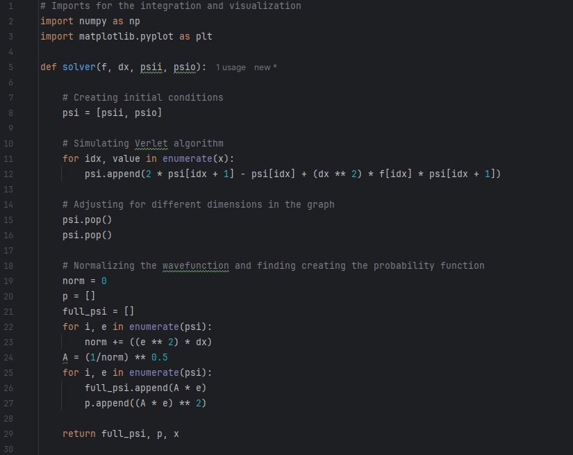
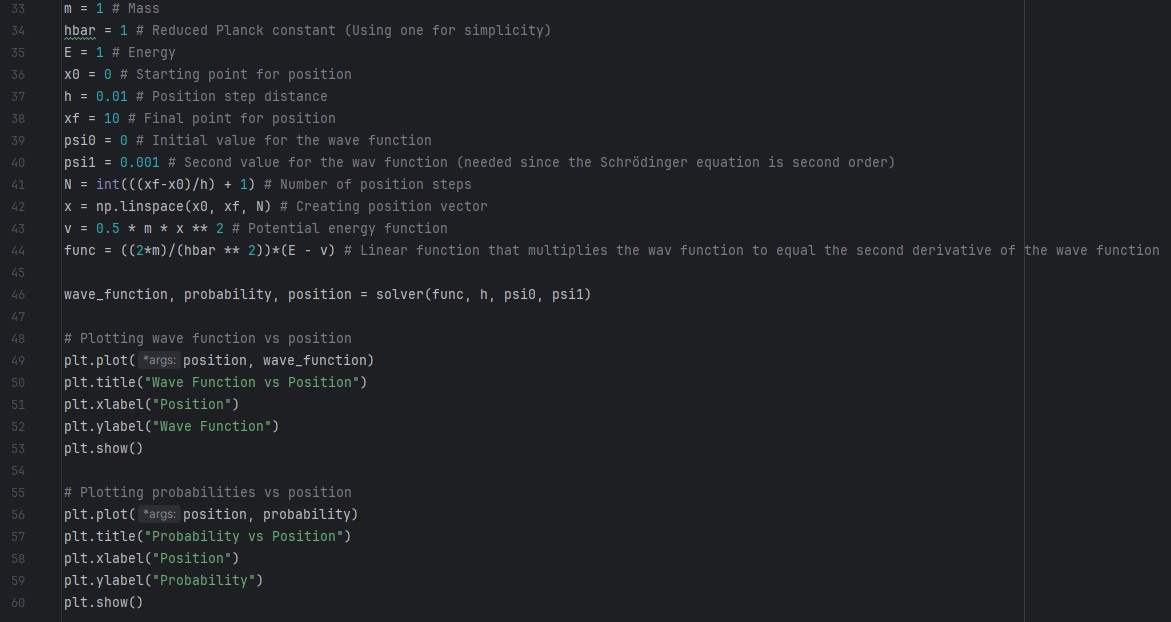
This project is a Python program that uses the Verlet algorithm to numerically solve the Schrodinger equation for normalizable eigenstates. I first created a vector/list that spans the target position interval with specified constant step distances using NumPy. I then created a second vector that contained two initial conditions (because the equation is second order) and ran these through the Verlet algorithm to find the remainder of the solutions for each value in the position vector. I then normalized the vector and used matplotlib to plot the wave function and probability distribution as a function of position. A picture of the code is below, and the GitHub repository can be found here:https://github.com/Oakers37/Schrodinger_Integrator
Top: Imports and the Verlet algorithm coded as a function. Bottom: Definitions of constants and functions, plugging these constants and values into the procedure, and graphing the solutions.
Skills Needed/Learned:
Quantum Mechanics
Differential Equations
Linear Algebra
Python
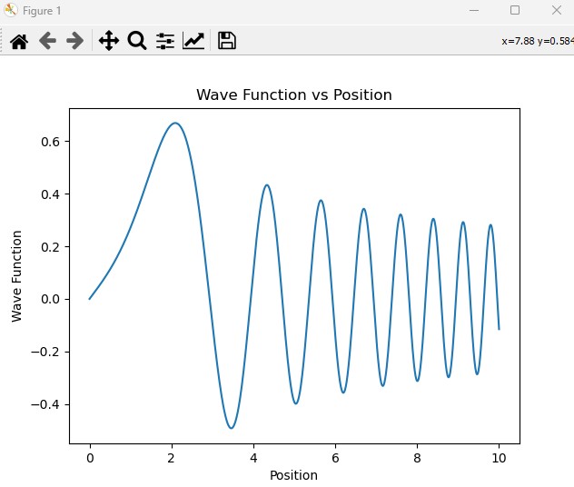
Results:
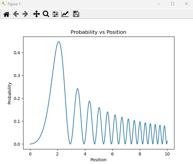
Left: A graph of the wave function versus position. Right: Graph of the probability of finding the particle in a given position.
Future:
I may look to find a way to include non-normalizable eigenstates as well as the normalizable ones. Since non-normalizable states propagate in complex spacetime, I will need to improve my Python graphing techniques to handle three or four dimensions.
Purpose:
I designed and built an Autonomous Niskin Deployment Mechanism (ANDM) as part of my internship at BIOS (Bermuda Institute of Ocean Sciences). The lead researcher was looking for an untethered way to collect deep-sea water samples from up to 3500 meters of depth for environmental DNA (eDNA) analysis. The advantage of this untethered design is that it saves money from having to buy kilometers of cable. This eDNA analysis is used to determine the fish that were present in that water sample within 48 hours, and that data is used to inform local protection plans.
Description:
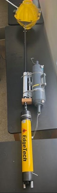
This design attached a Niskin (water sampler bottle) to a rig containing a float, carbon fiber rod, acoustic release, and sacrificial weight. This rig was repurposed from our Baited Remote Underwater Video Surveillance systems (BRUVS). The rig held all of the components together, allowing the system to sink, then resurface when we sent the signal to drop the sacrificial weight. The mechanism that I designed works by attaching the Niskin's trigger (which causes the Niskin to close) to the carbon fiber rod, then allowing the Niskin to slide over the rest of the rod independently from the trigger. While falling, the Niskin is pinned to its top position due to the greater downward force on the center rig than the Niskin itself. When the system hits the bottom, the tension in the rope connecting the sacrificial weight to the rest of the rig slacks, removing the additional downward force from the rig. This changes the force direction through the center rod to the upward direction while the force on the Niskin is still downward, triggering the water capture. Below is a picture of the whole system.
The top yellow part is the float; the middle mechanism is the Niskin with our modifications; the part that the Niskin mechanism is sliding over is the rigging tube for the BRUVS; the bottom yellow part is the acoustic release and the bottom of the acoustic release would hold the sacrificial weight. Together, the whole system is the ANDM.
Skills Needed/Learned:
Workshop Skills CAD Skills Math/Newtonian Physics
Results:
After creating the design, we tested it in 6 meters of water depth, which is what is seen in the video above. The Niskin remains open, allowing new water in for the duration of the descent; however, as soon as the system hits the bottom, the Niskin slams shut as expected, capturing the water sample at the bottom.
Future:
The design shown in the pictures is for a 5-liter Niskin, but I also designed an extra component for the 12-liter Niskin for more collection capability. Both designs are going to be used as the primary way of collecting deep-sea water samples as soon as the next round of funding is approved. An extension to this design would be to incorporate a microcontroller to trigger the closing when the system reaches a predefined depth for added versatility.
Purpose:
I received an Arduino self-balancing motorcycle kit. Rather than using the code provided in the kit, I decided to design my own so I could learn more about control systems.
Description:
This project is a desktop motorcycle. It runs off an Arduino Nano 33 IOT and is equipped with the Nano motor shield so the motors can be controlled. I developed the code to balance the motorcycle from scratch. I used Simulink and Matlab to develop a modified PID controller containing only the proportional and derivative terms. The code takes Euler angles and angular rate from the Arduino Nano's onboard IMU (Inertial Measurement Unit) and runs that through unit conversions and proportional gain blocks to scale the signals accordingly. It then sums these values up and converts them to values between 255 and -255 before running them into a motor that spins an inertial wheel that runs perpendicularly to the direction of the motorcycle. By the motor exerting a torque on the inertial wheel, an equal and opposite torque is exerted on the motorcycle from the inertial wheel. The PID controller feeds into this motor to correct for the motorcycle's tipping.
Skills Needed/Learned:
Matlab Simulink Systems Design Laplace Transform (For modeling) Wiring
Results:
A video of the motorcycle balancing itself by applying torque to the inertial wheel.
Future:
The future of this project would be to get the bike to balance when running through WiFi. This would give me the versatility to run it anywhere and not be constrained by the length of wire that I have. I would also like to try sizing this up and using more powerful motors.
Purpose:
There was always a big theft problem in my high school dorm. Frustratingly, I couldn’t even keep milk in the dorm kitchen, as it would disappear in less than a day. To solve this problem, I decided to make a lock for the milk.
Description:
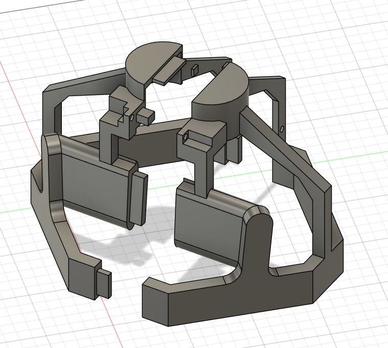
The lid for my specific milk jug did not have any indents or a screw cap, so I could not attach one there. Instead, the lock had to be two separate parts joined together by padlocks with a bar that passed through the handle of the milk jug so it could not be lifted. Below are the images.
Top:CAD of the lock. Bottom: Video of the lock in action.
Purpose:
My high school did not have an EZ-bar, which I like for training triceps and biceps. Rather than buying one, I decided to make one.
Description:
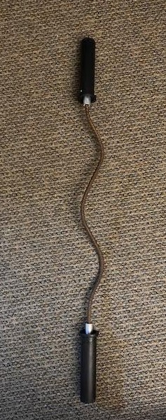
I bought some rebar online because it was very cheap, relatively bendable, and had a good enough grip. I then used a vise to bend the rebar into roughly equally segmented parts at roughly a 30-degree angle, as I found it to be the most comfortable. I then attached some barbell collars I found on Amazon to the ends using 3D-printed collars and metal pipes I found. I have tested out the barbell a few times, and it works very well for tricep training, but it is not as good for bicep training.
Future:
Since I have graduated from my high school, I donated this barbell to one of the students in my dorm. He actively uses this barbell in the gym to this day.
Purpose:
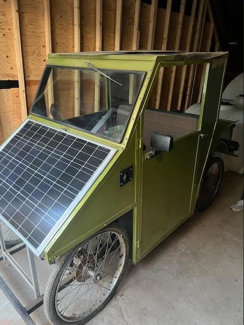
My school had an old solar car, which was a small electric car that was able to charge with on-board solar panels. Unfortunately, over the 20 years of sitting in a garage, many parts broke and needed repair. Our goal was to resurrect it while making a few upgrades.
Description:
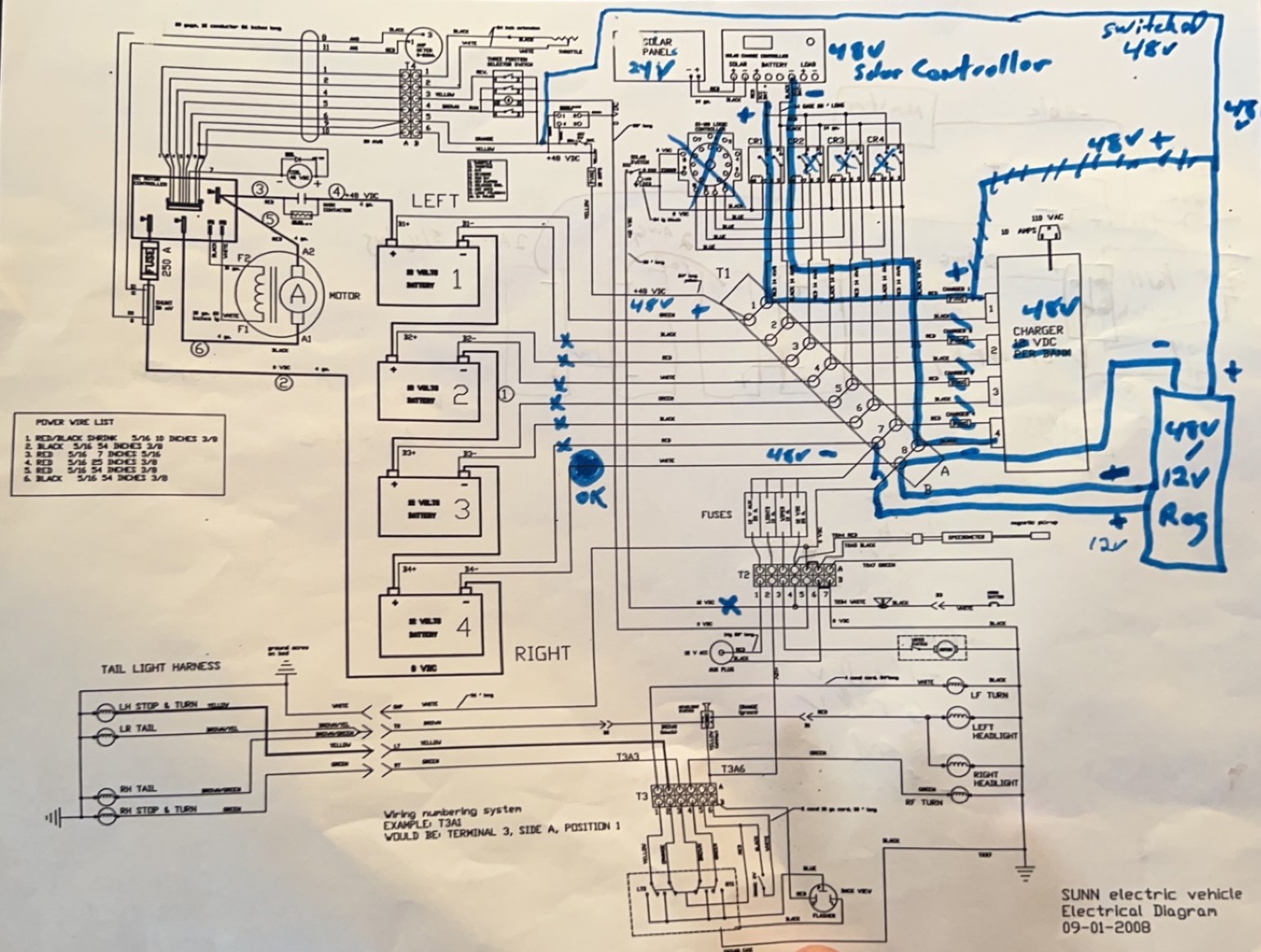
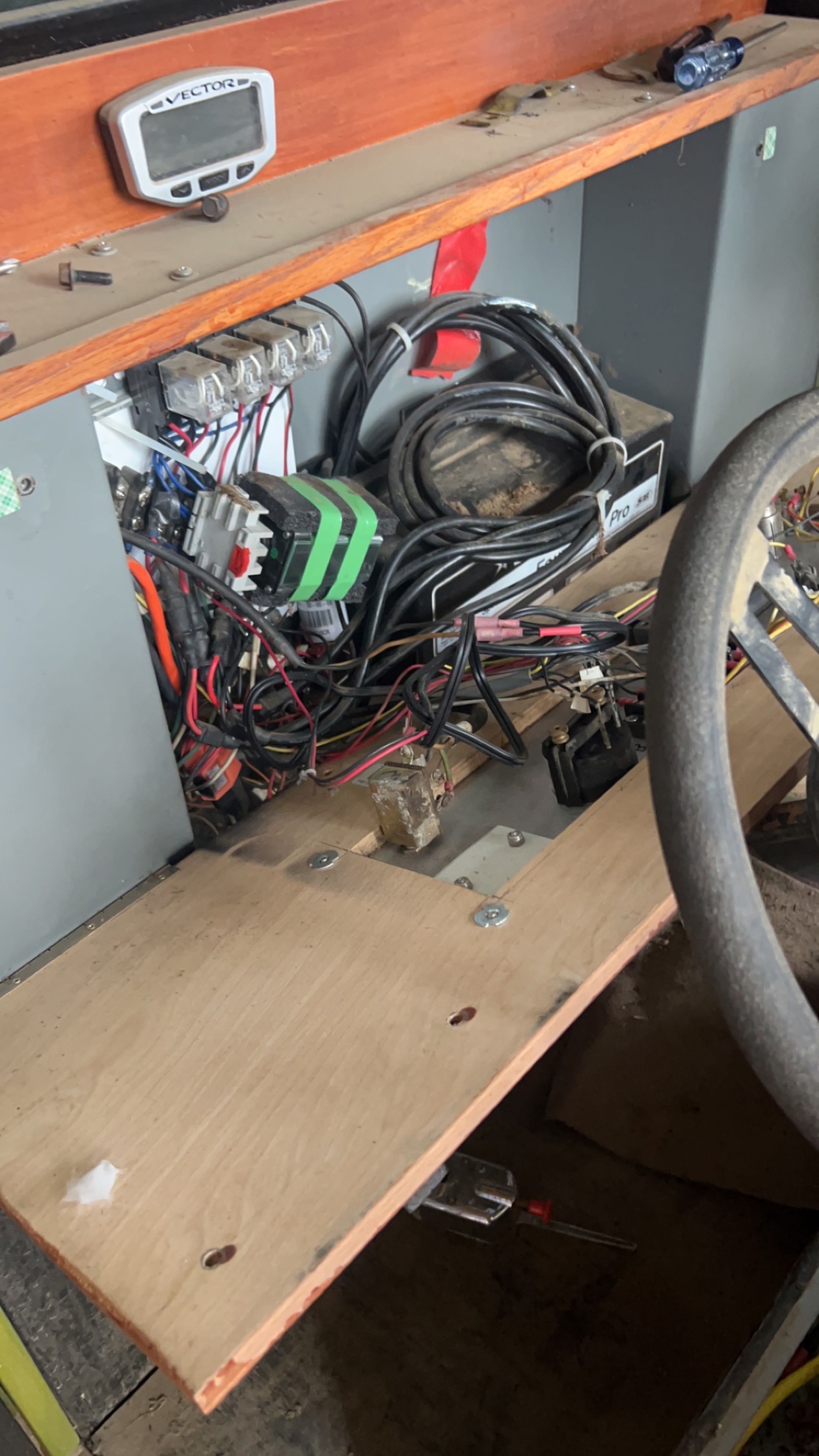
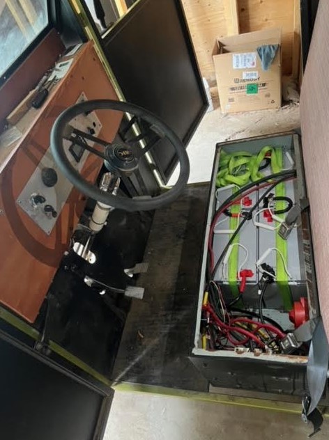
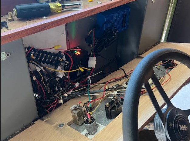
We changed the batteries and the charging architecture from parallel to series, decreasing the current running through the wire to increase safety and durability while still keeping the discharge in series. We also changed the solar and wall charge controllers to newer tech and removed many unnecessary wires. We replaced the ignition and key slot by combining them into one; finally, we replaced the speedometer and dashboard user interface. Below are the pictures of the car and the circuit diagram and the changes that we made.
Left: Wiring before our modifications. Right: Batteries after our modifications. Bottom: Wiring after our modifications.
Results:
We got the car to drive and charge properly. Below is a picture of the car being driven:
Future:
Now that this car is built, it can regain its title of a campus artifact. The next round of ambitious students could also consider upgrading the motor to reach higher speeds.
Publications
Abstract
This paper explores a specific optimization problem called the aircraft loading optimization problem. It is an optimization problem that can benefit from a quantum speedup by a quantum computer. This problem can benefit from a quantum speedup because it is part of an optimization class called QUBO problems. These problems can be expressed as a matrix-vector product. Quantum computers can convert this matrix into an Ising Hamiltonian and then perform quantum annealing to solve it. Unfortunately, these quantum computers are expensive and inaccessible, so this paper attempts to solve the aircraft loading optimization problem on accessible quantum computers or quantum simulators, using quantum-classical hybrid solvers. We used qiskit optimization to set up the problem and then tried multiple ways of solving it. The first was to simulate a quantum computer on our local hardware with qiskit, which inevitably failed because the problem was too large for the qiskit simulators. The second attempt was to use qiskit runtimes with IBM Quantum. This also failed because the packages were not compatible with qiskit optimization, making medium-size QUBO problems unsolvable by open-source quantum computing.